
The Hafner Technology Process Flow Diagrams & Component Descriptions
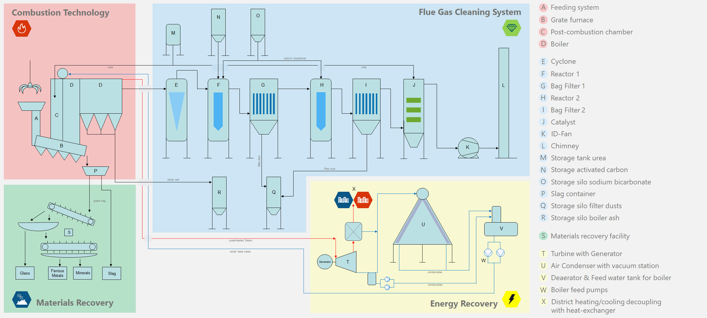
Process Flow Diagram – Grate Furnace
A - Waste Loading
Waste is sent to the combustion chamber often by means of an industrial grab and a continuous dosing conveyor.
The waste is poured into the loading hopper at the top of the water cooled loading channel, which – when it gets to the bottom of the channel – is then pushed to the furnace by the dynamically regulated feeder and introduced into said furnace through a closing shutter that prevents false air from leaking in (sludge is conveyed into the grate furnace directly by means of a pump, while liquid waste is pumped at high pressure directly into the incinerator and sprayed by special injector nozzles).
The supply systems permit continuous feed to prevent the forming of clogs and / or compact material lumps.
Depending on the type of waste, the feed order/geometry, components and process control are adjusted.
B - Grate Furnace
Over the feed ram the waste proceeds to the fire grate. The grate covering, which consists of several rows of fixed and moving (with forward and backward movements) alternating rows of grids conveys the furnace forward by lifting movements. The entire grate is divided into different grate zones in which the primary air (combustion air) is supplied evenly and demand-orientedly.
As a result, the waste is “dried”, “degassed”, “burned” and finally “sintered” to form slag in four process steps.
By constructive measures on the grate bars, a falling through of the ash particles is made possible by the grate. This ash is introduced into the slagger via through-feed funnels and conveyors.
The slag reaches the end of the grate through the discharge hopper into the wet slagger.
The entire grate firing is regulated by a hydraulic system.
C & D - Combustion Chamber with Boiler
Combustion Chamber (Fire Room)
The combustion process takes place in the combustion chamber, which is bounded below by the grate, on the sides and the ceiling by the cooled heating surfaces (membranes) of the boiler.
In the upper part of the combustion chamber secondary air is injected for swirling and homogenization of the flue gas flow in order to achieve a good combustion of the flue gases and to comply with the necessary residence times.
Control burners are positioned in the first quarter of the combustion chamber on the fume entrance side, while the temperature and O2 gauge is placed in the last quarter of the chamber near the fume exit.
SNCR-System (M – Additive Urea Storage)
Due to the nitrogen content in the waste, the high combustion temperatures and the residence times that are necessary to destroy organic compounds of the waste, as well as the oxygen content in the flue gas lead to the formation of nitrogen oxides (NOx).
To reduce NOx, the selective non-catalytic reduction (SNCR) method is used.
A urea-water mixture (reactant) is sprayed by metering pump and compressed air into the furnace at a temperature window of 850 to 1,100° C, thus making this reactant atomized.
Boiler
The boiler is a closed vessel (consisting of membrane walls, various heating surfaces, connecting pipes and drum), in which by the heat energy of the fuel (waste), water vapor is generated. This can be used outside the steam generator for power generation or for heat use (district heating or production steam).
Depending on the type of waste and thermal power, different boiler designs (vertical and horizontal boilers) can be put into operation.
Hafner’s “Large water boiler” works with natural water circulation (boiler system: natural circulation boiler). Part of the boiler is designed as radiation surfaces (membrane walls 1 ° to 3 ° radiation train) and part as convection surfaces (Evaporator, Economiser and Superheater).
The exhaust gases from the combustion chamber pass through the boiler and are cooled down to approx. 200° C.
The dust loads are deposited, as a result of the low flue gas velocities, in the radiation trains by gravity in funnels positioned underneath. In the convection parts, the dust loads stick to the tube bundles and are deposited by their own adapted mechanical cleaning devices in the funnels positioned below. Afterwards, the dust is transported to storage silos using suitable mechanical/pneumatic convoying systems.
P - Slag Container
The slag from the combustion chamber falls onto a water-bed feeder (Reedler) where they are cooled down and by means of the conveyor’s rotating mechanical scraper, they are conveyed to a large collection bin or to a recovery material station.
The flue gas that is produced during the incineration of residual waste is enriched with a wide variety of particulate and gaseous pollutants. Each pollutant emission means an interference with the natural composition of the atmosphere. In order to remove these substances as far as possible, the flue gas passes through various purification stages. Constant measurements are used to check the constant effectiveness of the individual cleaning stages. The typical Hafner system adopted is of the “Dry type” and has the following main components of the flue-cleaning: Cyclone, Absorption Reactor N. 1, Bag Filter N. 1, Subsequent Reactor N. 2, Bag Filter N. 2, Catalyst, ID-fan, and Chimney.
E - Cyclone
Cyclones are abatement systems that, without using moving parts and using appropriately shaped inlets, allow separation of the contaminating particles. In particular, the gas and dust stream is passed into a system consisting of two concentric cylinders. At the incoming gas a spiral motion is imposed in the gap between the two cylinders, from top to bottom.
The gases coming out from the boiler can exit through the inner cylinder, lower than the external one. The particles, having greater inertia with respect to the gas, will tend to bump against the walls of the outermost cylinder, and to fall on the bottom of the system, where a hopper for the recovery of the dust/ash is located (principle of operation is the centrifugal force).
The dust/ash can then be recovered for a subsequent treatment step.
F & H - Reactor 1 & 2
Depending on the plant design and emission control objectives, a Hafner waste incineration plant may have more than one reactor. The flue gases leaving the cyclone enter the vertical cylindrical housing of the reactor.
In the reactor, the adsorbents Sodium Bicarbonate and activated Carbon are injected to reduce the pollutants. The sodium bicarbonate is used to adsorb HCl, HF and SO2. The addition of activated carbon adsorbs dioxins, furans and volatile heavy metals.
The geometry of the reactor and the suitable residence time of the flue gases ensure good mixing of the flue gases with the additives.
The mixture of sodium bicarbonate (ground to 20 microns in the mill) and activated carbon is blown through a special tube into the right position on the reactor.
G & I - Bag Filter 1 & 2
The reaction that destroys the pollutants ends in the sleeve filter, mounted downstream from the reactor. The bag filter has a very high reducing efficiency and has the type of cells that can be excluded for the cleaning and maintenance operations. The Teflon filter sleeves (high specific weight filtering membrane) assure very high filtering capacity.
The resulting filter cake on the filter bags causes a secondary reaction between the unreacted or partially reacted sodium bicarbonate/activated carbon and still free gaseous pollutants (HCL, HF and SO2, dioxins, furans and volatile heavy metals).
The filter elements are mechanically cleaned in intervals by means of compressed air. The resulting filter dust is collected in a funnel below and transported by means of suitable conveyors in the storage silo.
J - Catalyst
The final stage of emission control is a DeNOX system. The catalyst consists of a honeycomb-shaped Full Catalyst based on metal oxides (WO3, V2O5) on a support of TiO2 in the form of Anatase.
The main task of the installed DeNOX system is the removal of dioxins and furans (PCDD and PCDF) and, secondarily, a part of the NOX.
K - ID-Fan
The variable speed fan with steel impeller, ensures the negative pressure necessary for the entire plant. The negative pressure in the furnace grate is adjusted by the PLC via Delta P instruments and with the variable speed fan under inverter control.
L - Chimney
The stack is made of stainless steel and insulated with aluminium lining. Every Hafner Waste to Energy plant has controllers whereby a number of parameters are constantly analyzed: CO, CO2, NOX, O2, HCL, SO2, TOC, dust, temperature, pressure, and volume flow-rate. Furthermore, the fumes coming from the ID-Fan in positive pressure are removed from the stack into the atmosphere.
The relevant data is transmitted to the PLC installed in the control room where they are processed, compared to 11% ratio of dry oxygen, displayed on the screen and printed daily.
M, N, O, P, Q & R - Additive Storage (Urea, Activated Carbon, Sodium Bicarbonate)
The following storage systems are provided for the residual waste collection and the necessary resources (additives) for the flue gas cleaning system:
– Sodium Bicarbonate Storage and Mill (Additive)
– Urea Storage Tank (Additive)
– Activated Carbon Storage (Additive)
– Ash Storage Silo (Residual)
– Dust Storage Silo (Residual)
– Storage of Residual Sodium Products (Residual)
– Slag Container/Bunker
S - Material Recovery Facility
Slag/Ash present in a domestic waste/hazardous waste Waste to Energy plant where wet discharge takes place presents a particular challenge for subsequent processing. High moisture levels and a metal content to which, predominantly, other material adheres demands a separation technology specially designed for the purpose. As an alternative, dry procedures are used for the ash removal in which metal separation in the fine grain range can generally be achieved more efficiently.
The slag/ash coming out from the incinerator will result in content which contains a particularly high proportion of recoverable heavy metals such as copper. Because electronic components with ever-smaller parts are being burnt along with municipal solid waste, a significant proportion of noble metals are also present.
The slags/ashes thrown out by the conveyor are taken to a material processing station where the raw materials still contained in the slag are recovered. The slag processing plant operates in several stages.
Materials recovered from reprocessing can be the following:
- Glass
- Ferrous Metals
- No ferrous Metals
- Stainless Steel
- Copper
- Precious Metals
- Minerals
T - Turbine with Generator
The steam turbine is usually comprised of a high-pressure and a low-pressure segment. Located between the two is an extraction steam valve.
Depending on quantity, pressure, and temperature, the main steam (which is usually saturated or superheated) activates the turbine wheels and the resulting mechanical power is transmitted to the generator which then produces electricity which is fed into the grid.
The exhaust steam from the turbine reaches the air condenser at, for example, 0.15 (a) bar and is subsequently cooled down and directed, as condensate, into the feed water tank.
U - Air Condenser with Vacuum Station
The steam at the outlet of the low pressure side of the turbine is conducted in an aerothermal condenser inside which the state changes from the gaseous to the liquid phase.
The air condenser consists of finned tubes (lamellar packs) in which condensate steam flows internally, lapped on the external surface by air at ambient temperature conveyed by appropriate fans.
The condensate is collected in a closed tank (a.k.a hotwell) placed under the air condenser and from here it is pumped into the deaerator positioned on the top of the boiler feed water tank.
V - Deaerator & Feed Water Tank for Boiler
The deaerator is a mechanical devices that remove dissolved gases from boiler feedwater. During the deaeration process, concentration of the dissolved carbon dioxide and oxygen is reduced to a level where corrosion is minimized; hence the steam generation system is protected from the harmful effects of corrosive gases.
To prevent corrosion, steam generation systems work with adequate pressure and a dissolved oxygen level of at least 5 parts per million (ppb) is required. However the dissolved carbon dioxide is essentially completely removed during the deaeration.
The deaerator uses steam to heat the water to the full saturation temperature corresponding to the steam pressure in the deaerator and to carry away dissolved gases. The deaeration system consists of deaeration tank, a storage tank and a vent.
W - Boiler Feed Pumps
Every steam boiler has two feedwater pumps. The pumps, one of which operates while the other is on stand-by are made of stainless steel and are fitted with the most important auxiliaries such as the suction filter, differential manometer, control valves, etc.
The pumps are equipped with an automatic recycling valve calibrated to the pump curve.
X - District Heating/Cooling with Heat Exchanger
Upon request from the clients, Hafner can install a heat exchanger to utilise the exhaust steam leaving the turbine – in part or in full – in order to give district heating and/or warm water.
Process Flow Diagram – Rotary Kiln
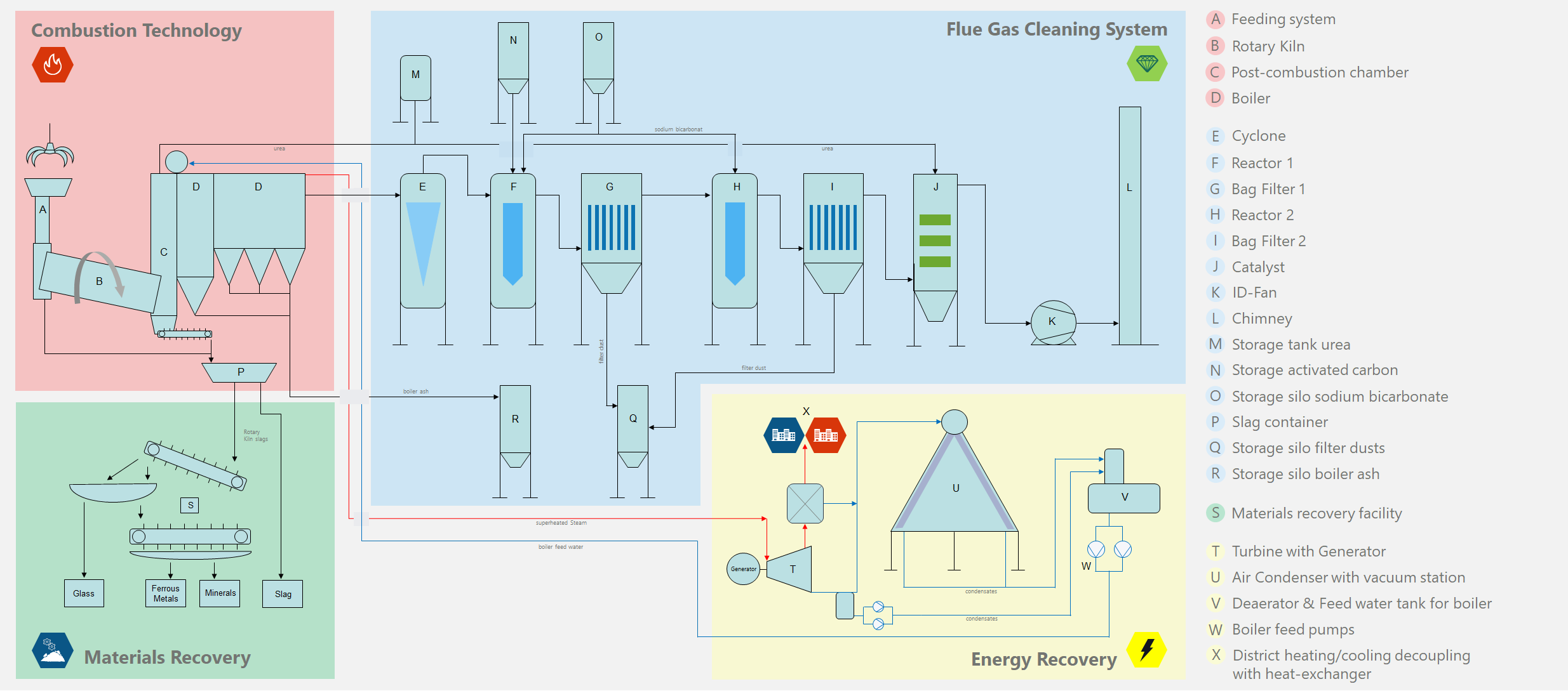
B - Rotary Kiln
The rotary kiln is made of carbon steel and fettling. The rotary furnace can be designed to incinerate waste with low and high calorific value. The waste stay time is adjustable by varying the rotation of the rotary drum.
In detail, the rotary furnace consists of a very thick metallic cylinder with high alumina content refractory lining and a manual speed reducer. The furnace is inclined by 2° on a horizontal plane while it rotates on four bearing rollers equipped with special bearings. It is also equipped with a number of guns and with a modulating burner (methane, gasoline, liquid waste) for triggering combustion and stabilizing the temperature.
Address
Via Giuseppe Di Vittorio 16
Bozen/South Tirol,
39100 - ITALY
Call Us
Phone: +39 0471 566 300
Business Dev.: +39 0471 566 331
Email Us
Secretary: info@hafner.it
Business Dev.: office@hafner.it